Nov 27, 2025
Motor Control
Table of Contents
1. Basics of Motors
2. Brushless Motor Control
	2a. Mosfet PWM Methods
	2b. Clarke and Park Transformations
	2c. Complete FOC Control Loop
Basics of Motors
Motors are essentially wires and permanent magnets placed in a fashion that allows the generated magnetic field from current to rotate the rotor. The simplest model of a motor is an inductor and resistor in series. Current going through the inductance generates a magnetic field, and also a backemf voltage that responds 90 degrees in phase after the current to oppose its change.
For a simple brushed dc motor with two wires (power and ground), the rotor speed and angle is controlled by varying the voltage magnitude and polarity between the wires. The voltage induces a current proportional to the wire resistance, creates a magnetic field component perpendicular to the rotor magnetic field to create torque. The maximum rotor speed is achieved when the backemf voltage from the inductance is equal to the applied voltage. The torque is proportional to the current through the wires or the magnetic field strength.
The higher the flux of the motor caused by more motor windings, magnetic poles, or stronger magnets, the higher the torque generated per unit current (torque constant, Kt). Conversely, speed increase per unit voltage (speed constant, Kv) is inversely proportional to the torque constant (Kt) since a weaker magnetic field induces less backemf voltage.
Controlling a brushed dc motor is easier and cheaper than brushless dc motors (BLDC). However, for higher torque applications like electric cars or robots, BLDC offers higher torque to weight ratio and efficiency to reduce the heat generated.
Brushless Motor Control
Torque control, the most basic control for a BLDC motor, passes a current reference which is proportional to torque, and calculates the required 3 phase voltages to get the desired current. Current is measured for torque control. The velocity control loop wraps the torque control loop, and position control wraps the velocity control loop. Both require position measurements from hall sensors or an encoder.
The most efficient control loop uses field oriented control (FOC), which optimizes the 3 phase voltages so the generated magnetic field component is 100% used to push the rotor.
Mosfet PWM Methods
Mosfets partially turn on and off to control the voltage and thus current of the motor. Each motor phase is connected in a half bridge configuration using a total of 6 mosfets for all 3 phases. FOC computes the required voltage components, but to realize these voltages, there are two common methods of generating these voltages using mosfets: sine pwm and space vector pwm.
Sine pwm makes each phase voltage follow a sine wave, which can easily be calculated from the phase voltages to produce a smooth torque profile. Typically, the 3 phases are connected in either wye (Y) or delta (\(\Delta\)) configurations which uses phase-to-phase voltages to generate current. Thus, only the relative voltages between each phase is important for torque. By measuring the voltage difference between the max and min phase voltages, sine pwm only uses uses 86.6% of the voltage range.
Space vector pwm improves this by ensuring that difference covers the entire voltage range for higher torque output and an improved torque profile. The amplitude of all the phase voltages is increased by \(\frac{1}{0.866} - 1 = 15.5%\) while a trapezoid signal is added to the sine profiles to ensure the voltages still stay in the voltage range. The resulting profile increases the phase voltage difference.
Sine pwm uses the desired 3 phase voltages, whereas space vector pwm uses the stationary coordinates (clarke frame) as inputs.
Clarke and Park Transformations
The clarke transformation converts the three phases of a BLDC motor into a 2 component stationary coordinate frame, \(I_\alpha\) and \(I_\beta\), usually where \(I_\alpha\) is aligned with the phase A current.
$$\begin{bmatrix} I_\alpha \\ I_\beta \end{bmatrix} = \frac{2}{3}\begin{bmatrix} 1 & \frac{-1}{2} & \frac{-1}{2} \\ 0 & \frac{\sqrt{3}}{2} & \frac{-\sqrt{3}}{2} \end{bmatrix} = \begin{bmatrix} I_a \\ I_b \\ I_c \end{bmatrix}$$
Using the park transformation, the clarke coordinates can be transformed into a rotating coordinate frame where \(I_q\) is the quadrature component of the magnetic field perpendicular to the rotor magnetic field that generates the torque, and \(I_d\) is the direct component that changes the existing rotor magnetic field. Ideally we want all the phase currents to convert to \(I_q\), and \(I_d\) to be zero.
$$\begin{bmatrix} I_d \\ I_q \end{bmatrix} = \begin{bmatrix} c(\theta) & s(\theta) \\ -s(\theta) & c(\theta) \end{bmatrix} = \begin{bmatrix} I_\alpha \\ I_\beta \end{bmatrix}$$
Note that the park and clark transformations applies for voltages too.
Complete FOC Control Loop
The following image shows the complete FOC control loop:
There is a control loop for both \(I_q\) and \(I_d\). Torque is compared to the actual \(I_q\) component and the error is fed into a controller to generate the desired voltage component \(V_q\). The same general control loop is implemented for \(I_d\), but the reference is always zero.
The inverse park transform combines these voltage components into stationary coordinates, \(V_\alpha\) and \(V_\beta\), which is directed used by space vector pwm to determine how to control the mosfets.
The resulting 3 phase currents are measured alongside the rotor position to be transformed into the clarke then park coordinates to calculate the error once again.
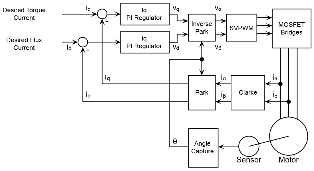
Table of Contents
1. Basics of Motors 2. Brushless Motor Control 2a. Mosfet PWM Methods 2b. Clarke and Park Transformations 2c. Complete FOC Control Loop
Basics of Motors
Motors are essentially wires and permanent magnets placed in a fashion that allows the generated magnetic field from current to rotate the rotor. The simplest model of a motor is an inductor and resistor in series. Current going through the inductance generates a magnetic field, and also a backemf voltage that responds 90 degrees in phase after the current to oppose its change. For a simple brushed dc motor with two wires (power and ground), the rotor speed and angle is controlled by varying the voltage magnitude and polarity between the wires. The voltage induces a current proportional to the wire resistance, creates a magnetic field component perpendicular to the rotor magnetic field to create torque. The maximum rotor speed is achieved when the backemf voltage from the inductance is equal to the applied voltage. The torque is proportional to the current through the wires or the magnetic field strength. The higher the flux of the motor caused by more motor windings, magnetic poles, or stronger magnets, the higher the torque generated per unit current (torque constant, Kt). Conversely, speed increase per unit voltage (speed constant, Kv) is inversely proportional to the torque constant (Kt) since a weaker magnetic field induces less backemf voltage. Controlling a brushed dc motor is easier and cheaper than brushless dc motors (BLDC). However, for higher torque applications like electric cars or robots, BLDC offers higher torque to weight ratio and efficiency to reduce the heat generated.Brushless Motor Control
Torque control, the most basic control for a BLDC motor, passes a current reference which is proportional to torque, and calculates the required 3 phase voltages to get the desired current. Current is measured for torque control. The velocity control loop wraps the torque control loop, and position control wraps the velocity control loop. Both require position measurements from hall sensors or an encoder. The most efficient control loop uses field oriented control (FOC), which optimizes the 3 phase voltages so the generated magnetic field component is 100% used to push the rotor.Mosfet PWM Methods
Mosfets partially turn on and off to control the voltage and thus current of the motor. Each motor phase is connected in a half bridge configuration using a total of 6 mosfets for all 3 phases. FOC computes the required voltage components, but to realize these voltages, there are two common methods of generating these voltages using mosfets: sine pwm and space vector pwm. Sine pwm makes each phase voltage follow a sine wave, which can easily be calculated from the phase voltages to produce a smooth torque profile. Typically, the 3 phases are connected in either wye (Y) or delta (\(\Delta\)) configurations which uses phase-to-phase voltages to generate current. Thus, only the relative voltages between each phase is important for torque. By measuring the voltage difference between the max and min phase voltages, sine pwm only uses uses 86.6% of the voltage range. Space vector pwm improves this by ensuring that difference covers the entire voltage range for higher torque output and an improved torque profile. The amplitude of all the phase voltages is increased by \(\frac{1}{0.866} - 1 = 15.5%\) while a trapezoid signal is added to the sine profiles to ensure the voltages still stay in the voltage range. The resulting profile increases the phase voltage difference. Sine pwm uses the desired 3 phase voltages, whereas space vector pwm uses the stationary coordinates (clarke frame) as inputs.Clarke and Park Transformations
The clarke transformation converts the three phases of a BLDC motor into a 2 component stationary coordinate frame, \(I_\alpha\) and \(I_\beta\), usually where \(I_\alpha\) is aligned with the phase A current. $$\begin{bmatrix} I_\alpha \\ I_\beta \end{bmatrix} = \frac{2}{3}\begin{bmatrix} 1 & \frac{-1}{2} & \frac{-1}{2} \\ 0 & \frac{\sqrt{3}}{2} & \frac{-\sqrt{3}}{2} \end{bmatrix} = \begin{bmatrix} I_a \\ I_b \\ I_c \end{bmatrix}$$ Using the park transformation, the clarke coordinates can be transformed into a rotating coordinate frame where \(I_q\) is the quadrature component of the magnetic field perpendicular to the rotor magnetic field that generates the torque, and \(I_d\) is the direct component that changes the existing rotor magnetic field. Ideally we want all the phase currents to convert to \(I_q\), and \(I_d\) to be zero. $$\begin{bmatrix} I_d \\ I_q \end{bmatrix} = \begin{bmatrix} c(\theta) & s(\theta) \\ -s(\theta) & c(\theta) \end{bmatrix} = \begin{bmatrix} I_\alpha \\ I_\beta \end{bmatrix}$$ Note that the park and clark transformations applies for voltages too.Complete FOC Control Loop
The following image shows the complete FOC control loop: There is a control loop for both \(I_q\) and \(I_d\). Torque is compared to the actual \(I_q\) component and the error is fed into a controller to generate the desired voltage component \(V_q\). The same general control loop is implemented for \(I_d\), but the reference is always zero. The inverse park transform combines these voltage components into stationary coordinates, \(V_\alpha\) and \(V_\beta\), which is directed used by space vector pwm to determine how to control the mosfets. The resulting 3 phase currents are measured alongside the rotor position to be transformed into the clarke then park coordinates to calculate the error once again.